

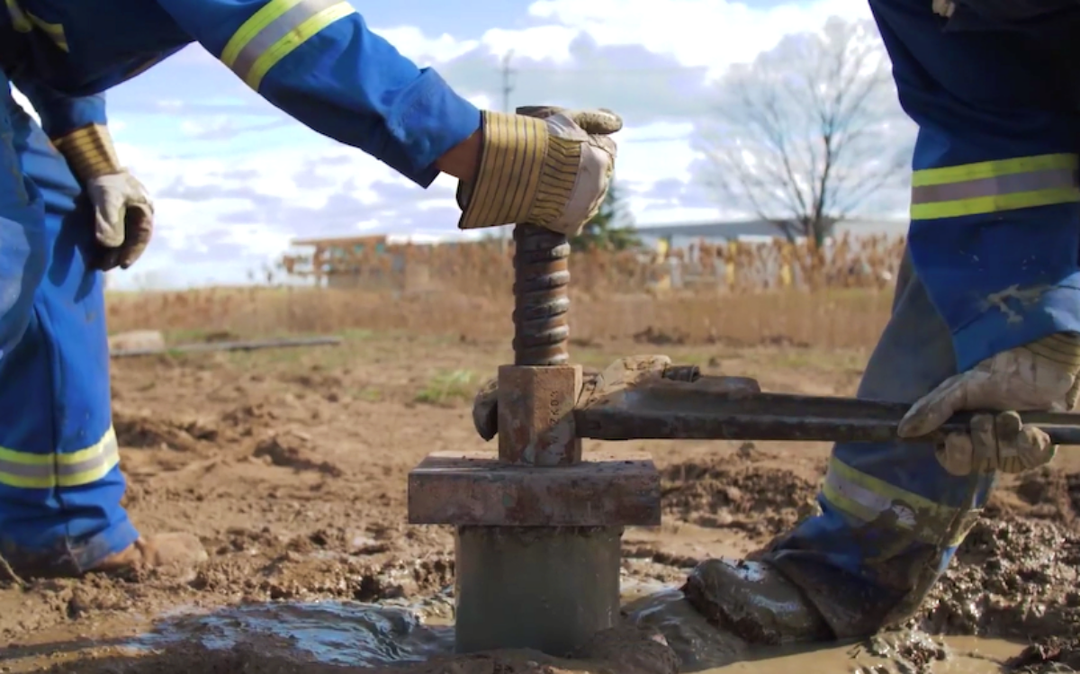
Table of Contents
Micropiles are small-diameter, drilled and grouted deep foundation elements used to support structures, transfer loads into competent ground, and improve foundation performance in challenging construction environments. Also known as mini piles or pin piles, micropiles are particularly useful where restricted access, limited overhead clearance, difficult subsurface conditions, or existing structures make conventional foundation construction impractical. A micropile foundation typically consists of a drilled hole, steel reinforcement, and cementitious grout, with structural loads transferred through the reinforced element into the surrounding soil or rock. Micropiles are used in new construction, foundation underpinning, seismic retrofitting, slope stabilization, and infrastructure rehabilitation. Their versatility makes them an important option for projects requiring specialized foundation solutions. However, successful micropile construction depends on geotechnical investigation, structural design, drilling methods, installation quality, load testing, and project-specific cost considerations.
What Are Micropiles?
Micropiles are high-capacity, small-diameter deep foundation elements installed by drilling into soil or rock and placing steel reinforcement and grout within the borehole. According to the Federal Highway Administration (FHWA), micropiles are commonly less than 300 millimeters (12 inches) in diameter, although larger diameters may be used in some applications.
Unlike conventional driven piles, drilled micropiles are installed using drilling equipment rather than impact driving. This allows contractors to construct foundation elements in areas where vibration, access limitations, or nearby structures create challenges for traditional piling methods.
Micropiles can transfer structural loads through a combination of grout-to-ground bond resistance and, where applicable, other load-transfer mechanisms. They can be designed to resist compression, tension, and lateral forces, depending on the reinforcement configuration, ground conditions, and structural requirements.
Main Components of a Micropile Foundation
A typical micropile foundation contains steel reinforcement, cementitious grout, and a load-transfer connection to the supported structure. The reinforcement may consist of a central steel bar, steel casing, or a combination of structural steel components.
The grout fills the drilled hole and provides a medium for transferring loads between the reinforcement and surrounding ground. In many micropile systems, load resistance is developed primarily through the bond between the grout body and the surrounding soil or rock.
Steel casing may be used to support unstable boreholes during drilling and can also serve as permanent structural reinforcement when incorporated into the design. The required casing length depends on ground conditions, structural loading, and the selected installation procedure.
How Micropiles Transfer Structural Loads
Micropiles transfer structural loads from the foundation into the surrounding ground through their reinforced grout bodies. Under axial compression or tension, load is transmitted through the steel and grout and subsequently transferred to soil or rock along the bonded length.
The available resistance depends on the grout-to-ground bond strength, micropile geometry, drilling technique, grouting method, and surrounding geological conditions. Because the bond resistance is influenced by installation procedures, micropile design must consider both geotechnical properties and construction methods.
Lateral load resistance involves additional factors, including bending stiffness, surrounding soil resistance, pile-head restraint, and the interaction between the micropile and supported structure. These factors must be evaluated together because lateral performance depends on the behavior of the complete foundation system rather than the micropile reinforcement alone.
Micropile Foundation Design
Micropile foundation design requires coordination between geotechnical and structural engineering. The designer must evaluate the loads imposed by the supported structure, the available subsurface resistance, the structural capacity of the micropile, and the expected foundation movements.
FHWA guidance addresses micropile design through both geotechnical and structural considerations. Foundation performance depends on the interaction between the installed micropile and surrounding ground, making site-specific investigation and appropriate construction methods essential.
Geotechnical Investigation
Subsurface investigation is essential before selecting a micropile foundation system. The investigation may include soil borings, rock coring, groundwater observations, laboratory testing, and other methods appropriate for the project.
The purpose is to identify suitable bearing or bond zones, determine soil and rock properties, evaluate groundwater conditions, and recognize potential drilling difficulties. The investigation also helps identify weak soil layers, weathered rock, voids, and other features that could affect installation or foundation performance.
For micropiles relying primarily on grout-to-ground bond resistance, the characteristics of the material surrounding the bonded length are particularly important. Groundwater, fractures, soil density, and rock quality may influence the achievable bond resistance.
Structural Capacity and Reinforcement
The structural capacity of a micropile depends on the properties and arrangement of its steel reinforcement, grout, and casing. Designers evaluate the ability of these components to resist the required axial, bending, and shear demands.
Micropiles subjected to compression must also be evaluated for potential instability where surrounding ground provides insufficient lateral support. This consideration can be important in very soft soils, voided ground, or other conditions where confinement is limited.
For tension-loaded micropiles, the design must address both the tensile capacity of the steel reinforcement and the ability of the bonded section to transfer the required load into the surrounding ground. Connections between reinforcement components must also provide adequate strength to transmit the design forces.
Micropile Spacing and Group Effects
Micropiles are frequently installed in groups beneath pile caps, foundation beams, or existing structural elements. The arrangement depends on the applied loads, available construction space, foundation geometry, and subsurface conditions.
When micropiles are installed close together, their load-transfer zones may interact. Group behavior can influence settlement, load distribution, and overall foundation performance.
The designer must also consider the structural connection between the micropiles and the supported foundation. Appropriate connection details are necessary to transfer compression, tension, and lateral forces safely.
Types of Micropiles
Micropiles are commonly classified according to their grouting methods. FHWA guidance describes several micropile construction types based on how grout is introduced into the borehole and whether additional pressure grouting is performed.
These classifications are important because grouting procedures can influence the bond developed between the micropile and surrounding ground. However, the classification alone does not establish the load capacity of an individual micropile.
Type A Micropiles
Type A micropiles are constructed using gravity grouting. After drilling and reinforcement installation, cementitious grout is placed within the borehole without intentional pressure grouting to enhance the grout-to-ground bond.
This method may be suitable where the surrounding ground can provide adequate bond resistance using gravity placement. The achievable capacity depends on the ground conditions, micropile dimensions, and construction quality.
Type B Micropiles
Type B micropiles use pressure grouting during grout placement. The grout is introduced under pressure as temporary casing is withdrawn or through another specified installation procedure.
Pressure grouting may improve grout contact with the surrounding ground and influence the development of bond resistance. However, the actual improvement depends on ground conditions and the effectiveness of the grouting operation.
Type C Micropiles
Type C micropiles involve primary grouting followed by additional grouting through a specialized system after the initial grout has been placed. This procedure allows further grout injection into the surrounding ground.
The method is intended to improve the grout-to-ground interaction where appropriate ground conditions and design requirements justify additional grouting operations. The timing, pressure, and sequence of grout injection must be compatible with the selected system and project specifications.
Type D Micropiles
Type D micropiles use post-grouting procedures that allow grout to be injected through designated ports or valves after initial grouting. These systems can provide greater control over the location and sequence of secondary grout injection.
Post-grouting can be useful where enhanced bond resistance is required, but the results depend on soil or rock conditions, grout pressures, installation procedures, and verification testing. The design should account for the construction method used to develop the required resistance.
Micropile Types and Construction Characteristics
The four micropile classifications describe different approaches to grout placement and bond development. The following table summarizes their principal construction characteristics and associated design considerations.
|
Micropile Type |
Grouting Method |
Construction Characteristics |
Primary Design Consideration |
|---|---|---|---|
|
Type A |
Gravity grouting |
Grout placed without intentional pressure enhancement |
Available grout-to-ground bond resistance |
|
Type B |
Pressure grouting |
Grout placed under pressure during construction |
Grout pressure, ground response, and bond development |
|
Type C |
Primary grouting followed by additional grouting |
Secondary grout injection after primary placement |
Grout distribution and bond enhancement |
|
Type D |
Controlled post-grouting |
Additional grout injected through designated ports or valves |
Post-grouting effectiveness and ground response |
The classification identifies the construction method rather than a guaranteed load capacity. Micropile performance must be established through appropriate design assumptions, construction controls, and testing.
Micropile Construction Process
Micropile construction generally involves preparing the work area, drilling the borehole, installing reinforcement, grouting, and completing the structural connection. The sequence may vary depending on the selected micropile type and subsurface conditions.
Construction procedures are particularly important because drilling and grouting directly affect the load-transfer mechanism. Contractors must follow the approved installation procedures and document conditions that could influence the completed foundation.
Site Preparation and Equipment Selection
Before drilling begins, micropile contractors evaluate site access, overhead clearance, working-platform conditions, underground utilities, and nearby structures. These considerations influence equipment selection, drilling arrangements, and construction sequencing.
One advantage of micropile construction is the availability of relatively compact drilling equipment. Specialized rigs can operate in locations where large conventional piling equipment cannot be accommodated.
However, restricted-access construction may require additional planning for grout supply, spoil removal, casing handling, reinforcement installation, and equipment positioning. The available working space must support safe and efficient construction operations.
Drilling the Micropile Borehole
Drilling creates the opening required for the micropile reinforcement and grout. The drilling method is selected according to soil or rock conditions, borehole diameter, required depth, and site limitations.
Rotary drilling, rotary-percussive drilling, and casing-supported methods may be used depending on the formation. Temporary casing is often necessary where unstable soil or groundwater conditions prevent the borehole from remaining open.
Drilling records can provide valuable information about subsurface conditions encountered during construction. Unexpected changes in drilling resistance, groundwater inflow, or material recovery may indicate conditions requiring engineering review.
Reinforcement Installation
After the borehole is prepared, steel reinforcement is installed according to the design requirements. Reinforcement may consist of threaded bars, steel casing, or combinations of steel components.
Centralizers and spacers may be used to maintain reinforcement alignment and grout cover. The reinforcement must be installed to the required depth and positioned to permit proper grout placement.
Connections between reinforcement segments must satisfy the structural requirements of the micropile. Couplers, welded connections, or other approved connection systems may be used depending on the reinforcement type and project specifications.
Grouting and Curing
Cementitious grout is placed within the borehole to create the micropile body and establish contact with the surrounding ground. The grouting procedure depends on whether the micropile is classified as Type A, B, C, or D.
Grout quality, placement continuity, pressure control, and construction sequencing are important factors affecting performance. The grout must develop sufficient strength before the micropile is subjected to the applicable testing or structural loads.
Curing requirements depend on the grout mixture, temperature, loading schedule, and project specifications. Contractors must coordinate installation and testing schedules with the required grout strength development.
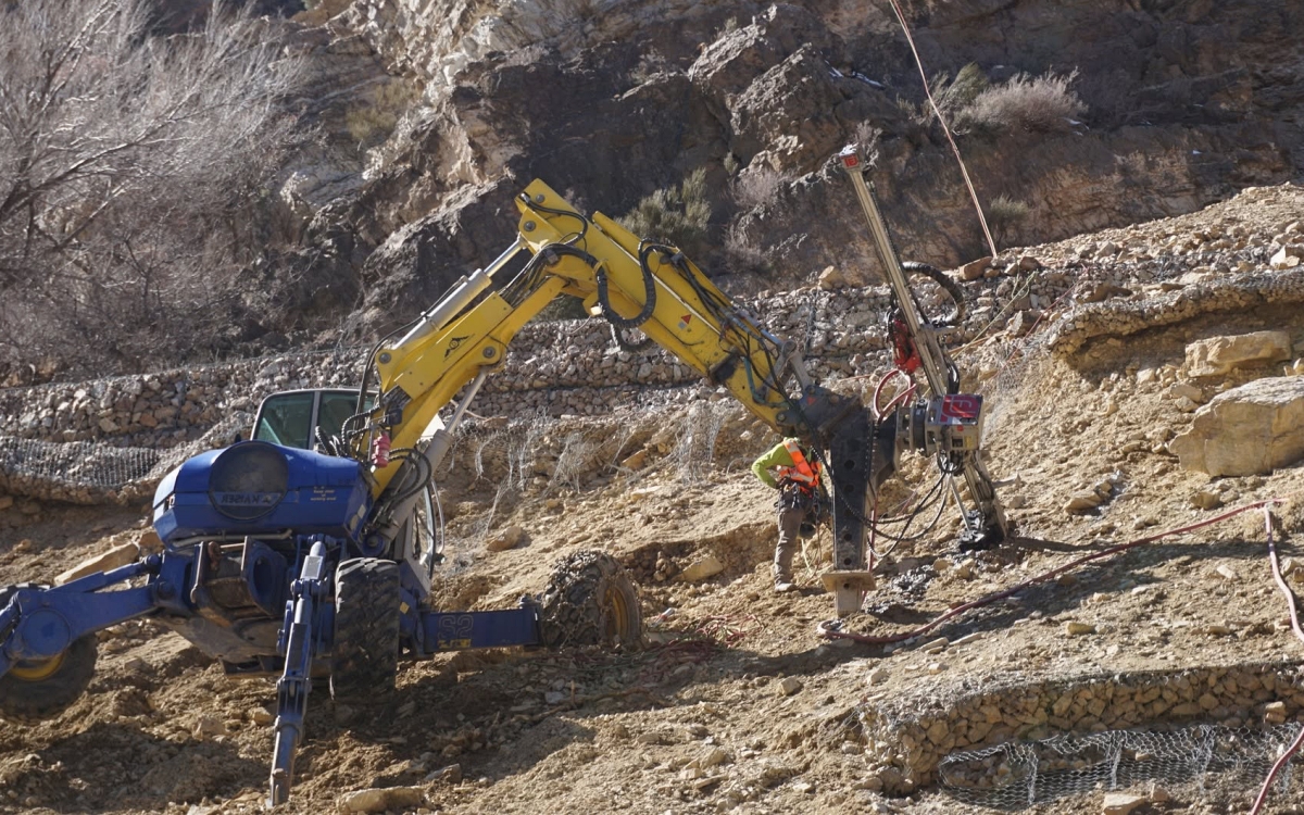
Micropiles are used for new foundations, underpinning, bridge rehabilitation, and other specialized geotechnical applications. Their installation using relatively compact drilling equipment makes them particularly useful in restricted-access environments. Photo Credit: TEI Rock Drills
Applications of Micropiles
Micropiles are used in a variety of foundation and geotechnical applications, particularly where conventional foundation construction is constrained by site conditions or existing infrastructure. Their relatively small drilling equipment, adaptable reinforcement arrangements, and ability to develop resistance in soil or rock make them suitable for specialized construction projects.
Foundation Underpinning
Foundation underpinning is one of the established applications of micropiles. Existing structures may require additional foundation support because of increased structural loads, foundation deterioration, settlement concerns, or changes in building use.
Micropiles can be installed adjacent to or through existing foundation elements and connected to the structure through specially designed transfer systems. This allows loads to be redirected into deeper or more competent ground.
Underpinning work requires careful evaluation of the existing structure, excavation effects, installation sequence, and load-transfer procedures. The design must account for both the new micropiles and the behavior of the original foundation.
Restricted-Access Construction
Micropiles are frequently considered where construction access is limited. Examples include building interiors, basements, areas beneath existing structures, and sites with restricted overhead clearance.
Smaller drilling equipment can make installation possible in locations that cannot accommodate conventional pile-driving equipment or large drilled-shaft rigs. This flexibility can be valuable for renovation and rehabilitation projects where existing structures must remain in place.
Nevertheless, equipment size is only one aspect of feasibility. Contractors must also consider material handling, ventilation, spoil removal, groundwater control, and safe access for personnel.
Bridge Foundation Rehabilitation
Micropiles can be used to strengthen or rehabilitate bridge foundations where additional capacity is required. They may also support new structural elements where existing infrastructure limits construction access.
Bridge applications require consideration of axial loads, lateral loads, scour conditions, foundation movements, and connections to existing or new structural components. The design must also account for the interaction between the new micropiles and existing foundation elements.
FHWA has documented micropile applications in transportation infrastructure, including foundation support and rehabilitation projects. These applications demonstrate how drilled micropiles can be incorporated into specialized transportation foundation systems.
Seismic Retrofitting
Micropiles may be incorporated into seismic retrofit projects to improve the foundation system’s ability to resist earthquake-related demands. Depending on the design, micropiles may provide additional axial resistance, uplift resistance, or foundation reinforcement.
However, seismic performance must be evaluated at the system level, including the supported structure, pile group, soil conditions, and connections. Micropiles are not inherently a complete seismic solution, and their contribution depends on appropriate engineering analysis and detailing.
Slope Stabilization
Micropiles may also be used in slope stabilization systems. In these applications, structural elements installed through potentially unstable ground can help resist movement and transfer forces into more stable material.
The design requires an understanding of the potential failure mechanism, soil or rock strength, groundwater conditions, and structural response of the reinforcement. Slope stabilization systems may incorporate micropiles alongside retaining structures, drainage measures, ground anchors, or other stabilization techniques.
Micropile Load Testing
Micropile load testing verifies whether the installed foundation elements satisfy specified performance requirements. Testing is particularly important because micropile resistance depends on both subsurface conditions and construction procedures.
FHWA guidance discusses verification testing and proof testing as part of micropile design and construction quality assurance. The required test procedures, loading levels, displacement measurements, and acceptance criteria depend on the governing project specifications.
Verification Load Testing
Verification testing is used to evaluate the suitability of the proposed micropile design and installation procedure. It may be performed on a test micropile before production installation or as otherwise required by the project specifications.
Verification tests can provide information about load-displacement behavior, bond resistance, and the ability of the installed micropile to sustain specified loading. The results may be used to confirm design assumptions or determine whether modifications to the construction procedure are necessary.
Proof Load Testing
Proof testing is generally performed on selected production micropiles to demonstrate compliance with specified load and movement requirements. A proof test applies controlled loading to the micropile while measuring displacement.
The test procedure, maximum load, hold periods, and acceptance criteria depend on the governing specifications. Proof testing helps verify that the installation process produces micropiles with acceptable performance under the required loading conditions.
Compression Load Testing
Compression load testing evaluates the response of a micropile subjected to downward axial loading. Loads are typically applied through a hydraulic jack and reaction system while movements are measured.
The test provides information about axial stiffness, load-displacement response, and the performance of the micropile under compression. Compression testing is particularly relevant for foundations supporting columns, walls, bridge elements, and other structures that transmit substantial vertical loads.
Tension Load Testing
Tension load testing evaluates the ability of a micropile to resist uplift or tensile forces. The applied load is resisted through the reinforcement, grout, and bonded section within the surrounding ground.
Tension tests can be useful for micropiles designed to resist uplift, overturning, or other tensile demands. Test interpretation must consider the required acceptance criteria, measured movements, and any time-dependent displacement specified for evaluation.
Lateral Load Testing
Lateral load testing evaluates the response of micropiles subjected to horizontal forces. The test can provide information about lateral stiffness, pile-head movement, and interaction between the micropile and surrounding ground.
Lateral resistance depends on several factors, including reinforcement stiffness, micropile diameter, soil properties, pile-head restraint, and loading conditions. Not every project requires lateral load testing, and the need depends on the design demands, project specifications, and the level of verification required.
Factors Affecting Micropile Foundation Costs
Micropile costs vary significantly between projects because installation conditions, foundation requirements, and construction methods differ. A meaningful cost estimate must consider more than the number of micropiles or the total drilled length.
Equipment access, drilling difficulty, reinforcement requirements, grouting procedures, testing, and construction sequencing can substantially influence project costs. Evaluating these factors together provides a more useful basis for comparing foundation alternatives.
Ground Conditions and Drilling Difficulty
Subsurface conditions are a major factor affecting micropile installation costs. Dense soil, hard rock, boulders, fractured formations, and groundwater can influence drilling productivity and equipment selection.
Unstable boreholes may require temporary casing or specialized drilling techniques. These measures can increase material use, equipment time, and labor requirements.
Unexpected ground conditions can also cause delays or require changes to the installation procedure. For this reason, geotechnical investigation and construction planning are important parts of micropile cost evaluation.
Micropile Diameter and Depth
Micropile dimensions affect drilling time, material quantities, reinforcement requirements, and grout consumption. Longer micropiles generally require additional drilling and materials, although the relationship between length and total cost is influenced by ground conditions and installation efficiency.
Diameter also affects the required equipment, casing size, reinforcement configuration, and grout volume. The most economical configuration depends on the required capacity and site-specific conditions.
Reinforcement and Material Requirements
Steel reinforcement can represent a significant component of micropile construction costs. The quantity and type of steel depend on structural loading, corrosion protection, pile length, and design requirements.
Projects requiring heavy casing, high-capacity reinforcement, specialized couplers, or additional corrosion protection may have higher material costs. Grout specifications and post-grouting requirements can also affect the total cost.
Access and Working Conditions
Restricted access can increase construction complexity even when micropiles are selected specifically because compact equipment can reach the work area. Interior work, low headroom, limited material storage, and difficult spoil removal may reduce productivity.
Specialized equipment or additional handling procedures may be required to accommodate these restrictions. Conversely, micropiles may provide an economical alternative when conventional piling methods would require extensive demolition, temporary works, or major access modifications.
Load Testing and Quality Assurance
Testing requirements influence project costs through equipment, labor, reaction systems, instrumentation, and scheduling. Verification testing may require dedicated test elements or additional construction arrangements.
Proof testing and other quality assurance procedures also require coordination with installation activities. Although testing adds direct project costs, it provides evidence that the installed micropiles satisfy the specified performance requirements.
Contractor Experience and Project Complexity
Micropile contractors must select drilling and grouting methods compatible with the ground conditions and design requirements. Contractor experience can influence equipment selection, installation planning, productivity, and the ability to respond to unexpected subsurface conditions.
Complex projects involving underpinning, restricted access, sensitive structures, or specialized grouting procedures may require additional engineering coordination and construction controls. These requirements should be considered when evaluating contractor proposals and total project costs.
Micropiles Compared to Conventional Deep Foundations
Micropiles and conventional deep foundations both transfer structural loads into the ground, but they differ in construction methods, equipment requirements, geometry, and typical applications. Understanding these differences helps engineers select a foundation system suited to the project’s loading and construction constraints.
Large-diameter drilled shafts can provide substantial structural capacity through relatively large foundation elements. Driven piles are installed by applying impact or vibratory energy, depending on the pile type and installation method.
Micropiles are installed by drilling and grouting, allowing them to be constructed using relatively compact equipment. This can be advantageous where access, overhead clearance, vibration, or existing structures constrain other methods.
However, micropiles are not automatically more economical or structurally preferable. Large projects with favorable access and ground conditions may be better suited to conventional piling systems.
The appropriate foundation solution depends on load requirements, ground conditions, constructability, environmental constraints, schedule, and total installed cost. These considerations should be evaluated together rather than relying on foundation diameter or installation method alone.
Selecting Micropile Contractors
Choosing qualified micropile contractors is important because installation methods directly influence foundation performance. Contractors should have experience with the anticipated ground conditions, micropile type, drilling equipment, reinforcement system, and grouting procedure.
Experience with restricted-access work or underpinning may be particularly relevant for rehabilitation projects. The contractor should also demonstrate the ability to meet the project’s documentation, quality control, and testing requirements.
Technical Experience and Equipment
The contractor should be capable of installing the required micropile diameter, depth, and reinforcement configuration under the expected site conditions. Equipment selection must account for drilling resistance, groundwater, access restrictions, and casing requirements.
Specialized equipment may be necessary for hard rock, unstable formations, or limited-headroom construction. The contractor’s proposed installation procedure should be compatible with the design assumptions and project specifications.
Quality Control and Testing Coordination
Micropile construction requires accurate records and consistent quality control. Contractors should document drilling conditions, reinforcement installation, grout placement, and other information required by the specifications.
Testing must be coordinated with the construction schedule and grout strength development. Where test results indicate unacceptable performance, the contractor and engineer must determine the appropriate corrective measures.
Clear communication between the specialty contractor, geotechnical engineer, structural engineer, and testing personnel supports effective construction quality management. This coordination is especially important when unexpected ground conditions require adjustments to the installation process.
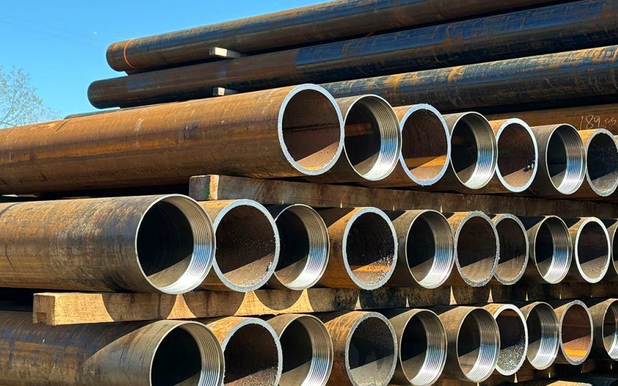
FHWA classifies micropiles into Types A, B, C, and D based on the grouting methods used during construction. These methods influence grout placement and the development of bond resistance between the micropile and surrounding ground. Photo Credit: John Lawrie Tubulars USA
Common Challenges in Micropile Construction
Micropile installation can encounter challenges associated with variable ground conditions, groundwater, restricted access, and construction tolerances. These challenges are not unique to micropiles, but their effects can be significant because micropile performance relies on the quality of a relatively small drilled and grouted element.
Unstable Boreholes
Loose or collapsing formations can make it difficult to maintain borehole geometry during drilling and reinforcement installation. Temporary casing or other stabilization measures may be required to prevent collapse and maintain the intended micropile dimensions.
The selected method should allow proper grout placement and avoid contamination of the bond zone. Contractors must also consider whether groundwater or soil movement could affect borehole stability during installation.
Groundwater and Grout Placement
Groundwater can affect drilling stability and grout placement. Flowing water, fractured rock, or highly permeable ground may create difficulties in maintaining grout continuity.
Construction procedures must account for these conditions through appropriate drilling, casing, and grouting methods. Grout losses or unexpected grout consumption should be evaluated because they may indicate ground conditions that differ from the original assumptions.
Installation Tolerances
Micropile alignment, location, and inclination affect structural connections and load transfer. Installation tolerances should be established in the project specifications and monitored during construction.
Significant deviations may require engineering review to determine whether the installed element remains acceptable. This is particularly important for micropiles installed beneath existing foundations or within closely spaced pile groups.
Long-Term Performance of Micropile Foundations
The long-term performance of a micropile foundation depends on structural capacity, geotechnical resistance, durability, and the behavior of the supported structure. These considerations are particularly important for permanent foundations expected to carry structural loads throughout their intended service life.
Corrosion protection is an important design consideration for permanent micropiles. The required protection depends on the anticipated service life, exposure conditions, ground aggressiveness, and applicable specifications.
Settlement and load distribution must also be considered, particularly when micropiles are installed to supplement existing foundations. The new and existing foundation elements may respond differently to applied loads.
Appropriate design, construction quality assurance, and load testing provide the basis for evaluating whether the foundation system can perform as intended. Long-term performance also depends on maintaining the integrity of structural connections and accounting for relevant environmental conditions.
Conclusion
Micropiles provide a versatile deep foundation solution for projects involving restricted access, difficult ground conditions, existing structures, and specialized structural requirements. Their relatively small diameter and drilled installation method make them particularly useful where conventional foundation construction may be impractical.
A successful micropile foundation requires more than selecting a drilling diameter or reinforcement size. Geotechnical investigation establishes the available ground resistance, structural design determines the required capacity, and construction procedures influence the bond developed between the grout and surrounding soil or rock.
Load testing provides an important means of verifying installed performance, while quality control helps maintain consistency throughout construction. Cost evaluation must consider ground conditions, drilling methods, reinforcement, access restrictions, testing requirements, and contractor capabilities.
For engineers, owners, and contractors evaluating mini piles or drilled micropiles, the most appropriate solution is one that satisfies the project’s structural and geotechnical requirements while accounting for construction feasibility, long-term performance, and total installed cost. Careful coordination among designers, specialty contractors, and testing personnel helps ensure that the selected micropile system meets the intended foundation performance requirements.